MPLS adalah suatu mekanisme untuk mempercepat routing process/packet delivery
Klo gw bilang ini suksesor nya ATM, X.25, dan Frame-Relay…MPLS itu kerjanya “ngasih” label
Contohnya deh:
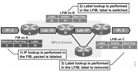
Jaringan MPLS klo udah fully converged kira2 kek gini (contoh router A mau ke network X pake label 25):
- Router A mau ke network X di router C, nah di A…untuk ke network X (berdasarkan ip routing yang dia punya) next-hop nya ke router B
- Nah, di router A…next-hop ke B itu akan di-mapping dengan label nomor 25, ini namanya impose action label (nempelin label), jadi klo mau ke network X, tinggal liat label-nya aja (label 25)
- Berdasarkan informasi yang ada di label 25…dikirimlah ke router B
- Nah, di router B, itu label 25 akan diliat…mau kemana…, oh ternyata mau ke network X
- Di router B, berdasarkan routing protocol yang dia punya, untuk ke network X itu lewat router C…dikasi label 47
- Di-mapping/swap/ganti-lah itu label 25 ke label 47, ini namanya label swapping/label switching
- Berdasarkan informasi yang ada di label 47…dikirimlah ke router C
- Di router C, network X itu ada di”diri dia sendiri” alias directly connected…nah, label 47 itu akan di-mapping ke “pop action label“, alias di remove label nya
Dari sini bisa kita liat, dengan MPLS kita dapat menempelkan “label” di A, nanti B, C & E tinggal nge-cek label nya aja (jadi ga perlu repot2 recursive lookup ke routing table, cek superior route, parent route, child route, longest match route…bla bla bla), udah jadi kek switch kecepatan transfer datanya, soalnya ga repot2 lookup sana-sini…
Cuma cek label, cek exit interface/next-hop ip, trus lempar….
Btw…itu tulisan FIB dan LFIB digambar apaan?!? Nanti dibawah dijelasin
Kok mirip ***IP CEF (Cisco Express Forwarding) yah? Ya, MPLS ini dibangun untuk menjembatani kecepatan switching (switch lebih cepet proses delivery-nya daripada router, dia cuma liat exit interface, “klo ada frame mau ke mac-address aaaa.bbbb.cccc lempar lewat port ini…“) dengan kemampuan routing-nya router (IP CEF ga bisa routing2an, yang handle kan OSPF,EIGRP, dll)
***IP CEF itu fitur Cisco untuk fast-switching, klo ada paket masuk ke switch/router, instead of searching through routing table, langsung aja…paket dengan IP X.X.X.X ini lempar lewat next-hop IP/exit-interface mana? (dengan FIB), ga pake acara liat routing table lagi (penjelasan lebih detil tentang CEF dibawah)…CEF di vendor lain namanya doang dibedain
Dah…gitu doang sih garis besarnya…
Sarannya, sebelum belajar MPLS…
- belajar BGP dulu
- IGP (OSPF bagusin pemahamannya)
- ngerti IP CEF
- VRF
- and a little bit about VPN
Udah ni?? Sumpe loe?!? wkwkkw…detailnya dibawah yaks…
=====================================
MPLS Labeling
Router/Switch yang jalanin MPLS disebut LSR (Label Switch Router)
Si A (dan C) yang nempelin (impose) label, remove (pop) label plus handling IP packet keluar-masuk MPLS disebut Edge LSR, ato klo di vendor lain dinamakan
LER (Label Edge Router)
IP Tujuan (Destination Network) didalam MPLS dinamakan FEC (Forward Equivalence Class)
Dari contoh diatas kita bisa ambil kesimpulan, proses delivery packet nya router2 di ISP itu CEPET banget kan (kecuali di edge LSR), Kek switching biasa…
Imagine klo semua router/switch cuma ngandelin routing table, ga kebayang CPU alat2 itu kerjanya kek apa
klo ga lemot…
pasti….

MPLS Label

MPLS label itu besarnya 4-byte (32 bit, 1 byte = 8 bit)
Dimana:
- 20 bit pertama adalah nomor label nya
- 3 bit selanjutnya (20 – 22) untuk IP Precedence atau CoS (Class of Service)
- 1 bit selanjutnya untuk nandain ada label lain ga? (multiple label/label stacking), klo disini diset (1) bukan (0), artinya ada lebih dari 1 label disini
- 8 bit terakhir untuk TTL (time-to-live), mirip kek TTL di IP Header kok
Wait…
20 bit pertama OK ane ngerti, 3 bit EXP untuk IP Precedence/CoS, bukannya ini QoS related field yah?? Yup…MPLS bisa buat QoS, bisa buat traffic engineering, bisa buat thesis…hahaha
Trus ada multiple label gituh dalam satu frame-packet?!? Oh iya dong…label yang satu untuk nandain jalur mana untuk keluar masuk, label yang satu lagi untuk nandain tunnel (VPN)
Maksudnya?? itu loh…klo lo pernah denger….MPLS VPN dengan MP-BGP (Multiprotocol BGP) dan MPLS TE (Traffic Engineering)
Nah, TTL nya itu kek gini:
- TTL Ingress (masuk ke MPLS Domain): value TTL di copy dari IP header ke label header
- TTL Egress (keluar dari MPLS Domain): value TTL di copy dari label header ke IP Header
TTL di MPLS bisa di-disable, biar di hide from costumer network, untuk alasan security juga, jadi costumer hanya bisa liat (ping) “ujung2″nya doang alias Edge LSR-nya aja
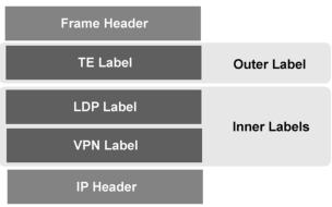
Nah, dari gambar diatas kita bisa liat…dimana MPLS Label itu “berada”
Kita liat simplified picture-nya dibawah:

MPLS itu tempatnya diatasnya Layer 2 (Frame), yang artinya MPLS dibawahnya layer 3 (IP)

Dibilang Layer 3…bukan (ga maen IP, Cuma asosiasikan label ke IP)
Dibilang Layer 2…aga kurang tepat (gunanya “nambahin” kapabilitas fungsi layer 2)
Makanya MPLS ini sering disebut Teknologi Layer 2,5
Untuk bisa nyebarin label itu ada 2 cara:
- Extend Functionality dari existing routing protocol
- Create protocol baru
Masalahnya klo pake cara pertama pasti susah (nambah header baru, belum lagi tipe routing protocolnya beda, plus bisa jadi ga kompatibel satu sama lain)
Makanya IETF (Internet Engineering Task Force) develops Label Exchange Protocol yang baru…
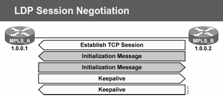
Yaitu LDP (Label Distribution Protocol), Dimana Label2 ini locally significant (jadi nomor2 label nya bisa beda2 tiap router/switch), MPLS Label nomor 0 – 15 itu reserved
***Dulu ada namanya TDP (Tag Distribution Protocol) punyanya cisco, Cuma yang kepake sekarang yang LDP (walaupun fungsinya sama persis)
LDP send hello messages every 5 second (via IP Multicast 224.0.0.2, UDP port 646, klo masing2 LSR itu directly connected), nanti pas nyambung…pake TCP
Bisa ga klo router nya ga saling terhubung langsung/bukan directly connected trus pake MPLS?? Bisa…pake LDP Targeted hello
(ada konfig nya)
=================================
MPLS Architecture
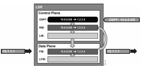
Ada 2 komponen utama dari MPLS, Control Plane & Data Plane

Control Plane = tempat LDP dan RIB (Routing Information Base, hasil komputasi/itung2an metric OSPF, BGP, EIGRP adanya disini, itu loh…”show ip route“) berada, mainly dikontrol oleh CPU Processing
Data Plane = Forwarding table, ada 2 Table:
- FIB: isinya table next-hop IP dan exit interface hasil proses Routing Table (ini yang digunain oleh IP CEF)
- LFIB: isinya table next-hop label hasil proses MPLS (jadi dia nge-cek label yang masuk, trus diasosiasikan ke label punya dia, yang mana exit interface dari label dia itu adalah hasil FIB nya), mainly dikontrol oleh ASIC (hardware buat switching)
Nah dari sini kita bisa liat problem yang kira2 bakal muncul klo kita konfig MPLS nya ga bener
- Paket yang sudah diberi label di drop, karena ga ada di LFIB (walaupun IP destinationnya ada di FIB)
- IP Paket (non-label) didrop, karena ga ada di FIB (walaupun di LFIB nya ada)
“Hardware processing lebih cepat daripada software processing”
LDP di control plane berfungsi untuk exchange labels dan menyimpan hasil exchange label2 itu ke LIB (Label Information Base). Informasi LIB inilah yang digunakan data plane untuk fungsi MPLS (LFIB)
Sebelum kita melangkah lebih jauh…mari kita liat arsitektur CEF dulu
Kinerja CEF itu kira2 kek gini:
-
Di Control Plane:
- Contoh: Ada rute dari OSPF tentang 10.0.0.0/8 masuk ke router LSR, di process lah itu rute
- Nah, nanti hasil prosesnya akan di store ke OSPF database (show ip ospf database)
- Berdasarkan hasil proses OSPF, diperoleh informasi dari OSPF yang menyatakan rute 10.0.0.0/8 ternyata best path-nya lewat 1.2.3.4 (misalkan), dimasukkanlah kedalam routing table (RIB, show ip route)
- Data hasil OSPF process ini (RIB) akan dimasukkan kedalam Data Plane
-
Di Data Plane:
- Informasi yang sudah di olah dari control plane, akan dimasukkan ke FIB
- Jadi, ketika ada paket mau ke 10.0.0.0/8 lagi (anggeplah ada IP tujuannya 10.1.1.1 mau masuk), router tidak akan liat routing table lagi
- Melainkan akan langsung liat…”ini 10.1.1.1 bisa gw kirim lewat mana…oh, lewat 1.2.3.4” di FIB-nya, kirim de…
jadi…klo Route Cache itu kan..dia harus via Control Plane dulu, baru paket selanjutnya langsung lewat data plane (kek Web Cache aja), nah…klo IP CEF itu, begitu OSPF selesai proses…hasil prosesnya langsung di-“capture” oleh CEF FIB di data plane, jadi ga usa nunggu2 packet pertama lewat Control Plane dulu
Nah, di MPLS, IP CEF ini ditambahin lagi dengan LDP:

- Informasi dari RIB akan dimasukkan kedalam CEF (FIB), disaat yang sama…rute 10.0.0.0/8 akan di kasi label (contoh label 25)
- Labeling ini juga di store di LFIB yang tempatnya sama dengan FIB, di data plane
- Jadi, klo ada paket dengan IP 10.1.1.1 akan dikasi label nomor 25 (misalnya) di LFIB, dimana label 25 itu diasosiasikan dengan next-hop IP 1.2.3.4 (yang ada di FIB)
- Nah, ketika data dikirim tinggal diliat deh labelnya, trus kirim
- Ketika sampai ke router seberang, di router seberang (IP 1.2.3.4), label itu akan di exchange (swap) labelnya dengan nomor 23 (misalnya)
- Nanti nomor 23 akan diliat…ini ke IP mana…
- Dan terus seperti itu sampe path terakhir/Edge LSR, di remove lah itu label …trus kirim de (ya liat routing table lagi klo FIB nya blum terupdate “populasi” rutenya)
Jalan yang harus ditempuh oleh LSR untuk kirim paket ber-label disebut LSP (Label Switched Path)
Biasanya jalan pergi dan jalan pulang LSP itu sama, tapi bisa aja beda (seperti MPLS TE)
Contoh klo pake IP aja…

Klo pake MPLS…
Nah, dalam MPLS ada yang disebut PHP (Penultimate Hop Popping), gunanya adalah untuk menghindari recursive lookup LFIB dan FIB
Tanpa PHP, Edge LSR akan proses buang label + proses lookup IP

Dengan PHP, router/switch sebelum Edge LSR akan remove label, nah si Edge LSR tinggal perform lookup IP
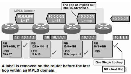
Jadi, singkat kata…sebelum nyampe ke Edge LSR, label-nya dibuang, jadi Edge LSR Router cuma proses IP CEF (pake FIB) nya aja, biar ga ribet kerja 2x
======================================
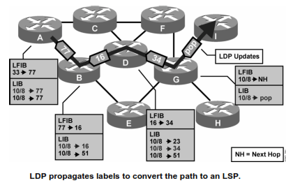
Distributing Label (How Labeling Works)
Router A mau ke Network X di Router D, anggeplah udah ada FIB nya, ternyata ke router B, kirim…
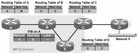
Pas dikirim…di router B, untuk network X, next-hop nya adalah router C (berdasarkan FIB), berdasarkan informasi itu di config-lah dengan label 25 untuk paket2 yang mau ke network X

Karena router B ga nerima/detect adanya paket labeling dari C, maka dia mengasumsikan bahwa dia adalah Edge LSR, di-pop deh (di remove labelnya pas mau ke C)
Karena masih initial, maka router B sebarin ini label 25 ke semua LSR (router2 yang jalanin MPLS), disini router B nyebarin ke A, C, dan E
(A, C, dan E juga sebarin masing2 label mereka klo ada, nanti baru pas convergence ketauan siapa yang impose, swap label, sama pop)

Nah, si A akan nerima bahwa network X itu di router B labelnya 25 maka FIB-nya si A akan diupdate (label 25), plus dibuatlah LFIB di data plane si A
Anaolgi yang sama juga di router C dan E
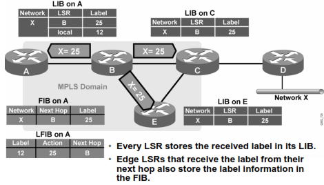
Nah, jadi seterusnya jika ada paket menuju network X dari router A, maka:
- Router A akan perform FIB aja, kasi label 12 (anggeplah A juga pake label), kirim ke router B
- Di router B, label 12 ini akan di ganti (label swapping) dengan label 25, *trus kirim ke router C (ato router E)
- Router C nge-detect bahwa dia yang terakhir ni, ga ada lagi next-hop untuk labelnya, dia remove/pop itu label, trus liat de FIB nya, kirim kemana ini paket
See…didalam MPLS domain uda ga ada lagi routing2an, lookup routing table lagi…semua pake label..cepet, di Edge LSR aja yang masih pake routing2an (tapi tetep…router2 yang ada di MPLS domain itu harus pake IGP dulu biar convergence…anggeplah untuk initialisasi aja, setelahnya pake label)
*kenapa hanya router C (ga ke router E)?? MPLS melihat dari LFIB bukan?!? Nah, LFIB ini liat next-hop IP nya kan dari FIB…sedangkan FIB ini informasinya dapet dari mana?? Ya dari routing protocol itu lah (RIB), jadi klo pake OSPF misalkan, kemungkinan ga akan dilempar ke E, tapi langsung ke C…trus ke D
==========================================================
MPLS VPN
Untuk tau MPLS VPN…ya kita harus tau MPLS…dan VPN itu sendiri
Mari kita refreshing tentang istilah2 berikut ini:
- Device konsumen yang terhubung ke ISP disebut CE (Customer Edge) ato CPE (Customer Premises Router)
- Device ISP yang terhubung ke konsumen disebut PE (Provider Edge)
- Device ISP yang tidak terhubung dengan konsumen (dan hanya konek ke router2 lain di ISP) disebut P (provider)
Dalam traditional WAN Network, PE biasanya Frame-Relay Switch/Router, di MPLS = Edge LSR
Dalam traditional WAN Network, P biasanya core/transit router, di MPLS = LSR
Contoh desain MPLS VPN:

MPLS membagi jaringan menjadi 2 buah terminologi:
- C-Network (Customer Controlled network)
- P-Network (Provider Controlled network)
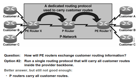
Ada 3 opsi agar PE router bisa carry customer routing information:
Opsi 1.

Opsi 2.
Opsi 3. (Best Solution)

Tapi kan Opsi 3 harus pake routing protocol dong?? Gimana X tau harus ke Y??…nah, disinilah BGP berperan
Internal P-Network bisa pake IGP (OSPF,EIGRP, ato IS-IS), untuk X dan Y (PE Router) bisa pake BGP (i-BGP tepatnya)
Jadi route2 customer ga dibawa masuk kedalam jaringan P-Network plus BGP adalah routing protocol paling efektif untuk handle route2 dengan tipe permasalahan kek gini
Eh…tapi kan bisa aja customer A pake 10.0.0.0/8 dan customer B juga pake prefix yang sama…gimana cara BGP bedainnya?! Dengan VRF (Virtual Routing dan Forwarding)
Apaan lagi itu VRF…Biasanya kan kita klo di CCNA Class/CNAP Class cuma setting HQ ke Branch via RIP (ato OSPF/EIGRP misalkan) untuk company A, dimana company A untuk IP private nya 10.0.0.0/172.16.0.0/ato 192.168.0.0, nah bagaimana klo ada company B juga pake IP yang sama (emang A doang yang bole pake IP Private? Engga kan)

Nah, VRF itu gunanya buat mengatasi masalah ini, sebuah router (biasanya PE) akan punya lebih dari 1 routing table (satu buat A, yang satu lagi buat B)
Caranya gimana biar router PE bisa tau yang mana rute punya A, yang mana rute punya B? dengan mengasosiasikan routing table dengan inbound interface nya (jadi nge-cek interface nya….int fa0/1 pake VRF company A, int fa0/2 pake VRF company B)
Cara VRF mengasosiasikan IP interface yang ber-IP sama (yang sama2 32-bit, 1 interface buat A dan satu lagi buat B) adalah dengan cara membuat RD (Route Distinguisher)
RD bikin 32-bit customer IPv4 address jadi 96-bit unique address (jadi RD itu besarnya 64-bit), Untuk IPv6 VPN juga sama…nambahin 64-bit juga
Nah…96-bit itulah yang jadi alamat RD, biasanya dipake untuk VPNv4 (VPN IPv4) address, alamat VPN inilah yang dipake BGP untuk nganterin data via MPLS, RD hanya bisa mengasosiasikan diri dengan 1 buah rute VPN
Klo customer yang punya 2 atau lebih VPN (kek 1 buat data, 1 lagi buat VoIP VPN) gimana dong?
RD akan ditambahin fitur RT (Route Target)
Caranya?? value dari RT ini akan di-attach ke VPNv4 BGP (RD) untuk mengindikasikan route membership terhadap suatu route/jaringan (kasarnya RD:RT 1 buat VPN Data dan RD:RT 2 buat Voice)
Nah…value ini akan di Carry BGP melalui BGP Community (extended, dengan keyword send-community [option]), BGP yang udah carry informasi “modified” IPv4 ini disebut MP-BGP (Multiprotocol BGP)
(Abis ketik “router bgp [as number]“, untuk jalanin MP-BGP kita harus ketik “address-family vpnv4“)

For summary, MP-BGP carries information below:
- Modified IPv4 address = VPNv4 address
- Extended BGP Community value = RT (Route Target)
- VPN Label (MPLS VPN) and LDP Label
- BGP attributes itself (such as AS-PATH)
Dari sini kita bisa liat, customer dan PE bisa punya beberapa “routing table” (tepatnya forwarding table, contoh: 1 buat VPN data, 1 lagi buat voice VPN), inilah yang disebut VRF
MPLS VPN Label Distribution

Ketika paket masuk ke ingress router, dia akan ngasi VPN label, trus kirim across P-Network, tujuannya ke egress router
Setelah sampai di egress router, dia akan bilang “oh iya, ini label emang tujuannya ke gw…tapi harus gw buang kemana ini label?”
(pake VRF yang mana?!?) hasilnya, ini paket di drop
Oleh karena itu dibuatlah MPLS Label Stacking (label lebih dari 1, yang awal2 uda gw jelasin), satu untuk nandain jalur VPN untuk Ingress dan Egress, satu lagi untuk nandain jalan keluar/masuknya label didalam P-Network

Nah, disini paket yang mau masuk akan di kasi label VPN, dari Ingress ke Egress akan dikirim pake LDP Label, begitu di Egress itu LDP label-nya di pop/remove, dia akan liat label satunya lagi (VPN)…”oh…lempar ke CE router toh…” jadi ada 2 VRF (1 VPN alias Exit Route dan 1 buat LSP-nya)
Di MPLS VPN juga bisa pake PHP, jadi sebelum sampe egress router…label LDP nya uda di pop, hasilnya egress router hanya perform label VPN lookup aja
(for my note: klo router customer pake non-BGP untuk nyambungin ke PE, contohlah RIP…itu RIP harus di redistribusi ke BGP…”ya iyalah, Ingress & Egress router nya aja pake BGP“, kecuali pake OSPF…bisa pake super backbone atau sham-link, see OSPF (tulisan paling bawah))
===========================================================
MPLS TE (Traffic Engineering)
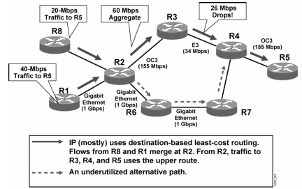
MPLS TE adalah MPLS yang menerapkan metode “manipulasi traffic” untuk data2 yang mengalir via MPLS
Biasanya digunakan untuk Voice Traffic (VoIP), untuk menghemat cost alias menghemat bandwidth. Dan biasanya klo uda nyinggung kata2 menghemat bandwidth, voice traffic, ato manipulasi traffic load…mau ga mau kita akan menyinggung QoS dan IP SLA
Dengan MPLS TE kita bisa bikin traffic yang berbeda LSP nya
Contoh:
Tanpa MPLS TE
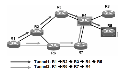
Dengan MPLS TE

Nah, karakteristiknya sama nih ama MPLS VPN, harus punya 2 label…1 label untuk in/out MPLS Domain, 1 label untuk LSP-nya (namanya traffic tunnel)
LSP dari MPLS TE bisa di-create dan di maintain lewat RSVP (Resource Reservation Protocol) – belajar di QoS ini
Untuk mengoptimalkan LSP dari MPLS TE ini kita bisa pake CBR (Constraint-based routing) metric
Contohnya kira2 begini:
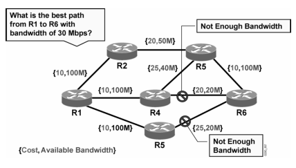
CBR ini memakai algorithma modifikasi dari Djikstra (SPF – Shortest Path First), yaitu Constraint SPF (CSPF)
CBR inilah yang berfungsi untuk mengoptimalkan LSP baik optimum path, physical link availability, maupun Path maintenance
====================================================
Wokeh…that’s all about MPLS Theory
Met Puasa…Met Idul Fitri…
Abis puasa (tepatnya abis kelar sidang thesis) kita lanjut konfigurasinya
Mudah2an catetan gw berguna untuk semua yang mau (atau sedang terjun) dalam MPLS
**********
References:
- RFC 3031, MPLS Architecture
- Implementing Cisco MPLS Student Guide
- Cisco MPLS Foundation Guide
next-hop