

Hmmm….Layer 5,6,7 udah…Transport yang Layer 4 udah, Network di Layer 3 udah
Kali ini kita akan belajar yang namanya Data Link…dimana tuh ?? Layer 2
Data Link menyediakan pengaturan untuk exchanging data over local media (Layer Data Link menyediakan service untuk mensupport proses komunikasi dari setiap medium ketika data di transmit/dikirim)
2 Service Basic/Dasar dari Data Link Layer adalah:
- Allows the upper layers to access the media using techniques such as framing
- Controls how data is placed onto the media and is received from the media using techniques such as media access control (MAC) and error detection
Terminologi2 yang ada di Layer 2 – Data Link
- Switch: Alat ini BIASA nya ada di layer 2 (walaupun switch2 “canggih” bisa di Layer 3), contoh Layer 2: Switch Cisco Catalyst 2950, Layer 3 Switch / Multilayer Switch: Switch Cisco Catalyst 3650.
- Frame: PDU dari Data Link Layer (remember *encapsulation)
- Node: istilah Layer 2 untuk network devices yang terkoneksi dengan media yang sama (media penghantar yang sama)
- Media/medium (physical) – The physical means for the transfer of information between two nodes
- Network (physical) – Two or more nodes connected to a common medium
Data Link Layer – Frame
Protocol Data Link layer require control information untuk membuat protocol bekerja. Control information may tell:
- Which nodes are in communication with each other
- When communication between individual nodes begins and when it ends
- Which errors occurred while the nodes communicated
- Which nodes will communicate next
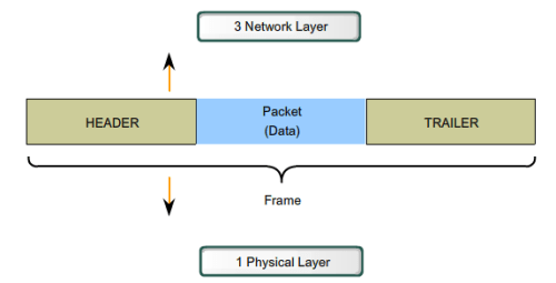
The Data Link layer prepares a packet for transport across the local media by encapsulating it with a header and a trailer to create a frame.
Data Link layer frame includes:
- Data – The packet from the Network layer
- Header – Contains control information, such as addressing, and is located at the beginning of the PDU
- Trailer – Contains control information added to the end of the PDU
Bahasa mudahnya adalah : Data Link layer bertugas menghubungkan antara physical/hardware layer dengan logical/software layer (network layer keatas) dengan menyediakan protocol, encapsulasi, dll
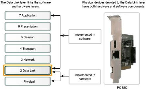
Data Link Sub Layer
- Upper Layer : defines the software processes that provide services to the Network layer protocols –> LLC (Logical Link Control)
- Lower Layer : defines the media access processes performed by the hardware –> MAC (Media Access Control)
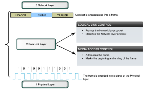
Memisahkan Data Link Layer kedalam sublayer memungkinkan 1 tipe frame di define oleh upper layer (seperti Network Layer) untuk mengakses different type of medium yang di define oleh lower layer (Physical layer), Such is the case in many LAN technologies, including Ethernet
Let’s see these sublayers in brief view:
-
Logical Link Control
Logical Link Control (LLC) menaruh informasi di frame yang mengidentifikasikan Network layer protocol mana yang sedang digunakan di frame. This information allows multiple Layer 3 protocols, such as IP and IPX, to utilize the same network interface and media.
-
Media Access Control
Media Access Control (MAC) provides Data Link layer addressing and delimiting of data according to the physical signaling requirements of the medium and the type of Data Link layer protocol in use. Mengatur placement data frame kedalam media
Media Access Control (MAC) berguna untuk mendefinisikan proses2 apa sajakah dari setiap network device yang bisa mengakses network media dan mentransmit frames di lingkungan network yang berbeda.
Media Access Control tuh kek ibarat Aturan2 Lalu Lintas yang mengatur keluar masuknya kendaraan di jalan raya. Ketidak hadiran dari MAC ini akan berakibat kendaraan2 yang ada memasuki jalan raya tanpa perduli dengan kendaraan lain (bodo amat beybeh)
Tapi, tidak semua jalan raya dan entrance itu sama. Traffic di jalan raya (kendaraan2) dapat memasuki jalan dengan merging (1 jalan digabung), pake lampu lalu lintas (biar ga macet). Pengemudi mengikuti set aturan2 dari jalan2 yang ada (klo jalannya hanya bole 1 arah…ya satu arah…jgn ngelawan arah 😛 )
The method of media access control used depends on:
- Media sharing – If and how the nodes share the media
- Topology – How the connection between the nodes appears to the Data Link layer
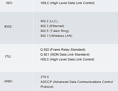
Standard2 dalam Data Link Layer

There are two basic media access control methods for shared media:
- Controlled – Each node has its own time to use the medium
- Contention-based – All nodes compete for the use of the medium
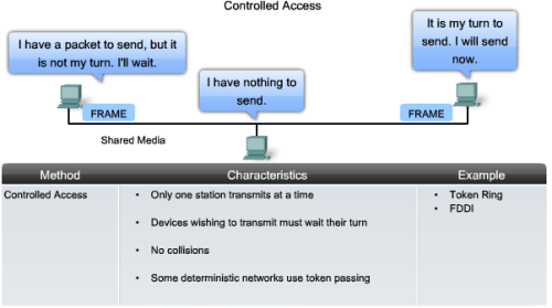
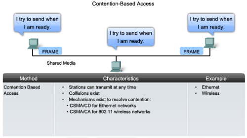
CSMA: Carrier Sense Multiple Access, Sebuah protocol dimana node yang mo mentransmit data harus men-“listen” sinyal carrier (yaitu sinyal yang menandakan bahwa ada node lain yang lagi transmit data), jika ada…maka node tersebut nunggu sampe sinyal itu hilang/tidak ada
-
CD : Collision Detection
Contohnya adalah CSMA itu sendiri
-
CA : Collision Avoidance
Bedanya adalah, ketika sinyal carrier ga ada, host yang intent to send data, kirim pesan “HOI, gw mo kirim data, jgn ada yang make yaaaa” wkwkkw (CSMA/CD = jika sinyal ga ada…langsung try sending, ga pake tegor2an dulu)
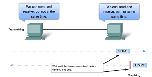
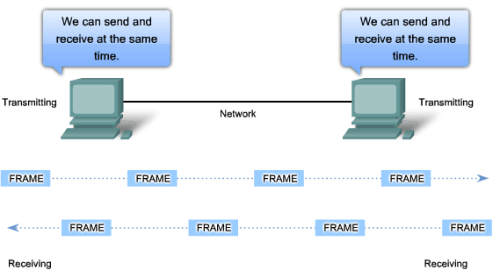
There are two basic media access control methods for non-shared media:
-
Half Duplex: (pake gambar aja de..males gw ngetiknya)
-
Full Duplex:
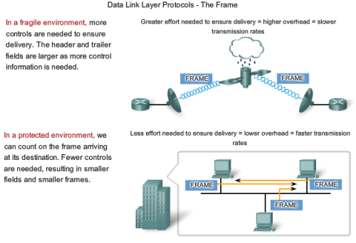
Membahas data link berarti membahas pula tentang topology, khususnya Logical Topology
- The physical topology is an arrangement of the nodes and the physical connections between them. The representation of how the media is used to interconnect the devices is the physical topology (configurasi kabel, PC, dan alat2 jaringan)
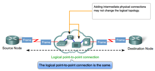
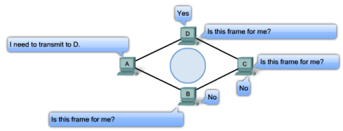
- A logical topology is the way a network transfers frames from one node to the next. This arrangement consists of virtual connections between the nodes of a network independent of their physical layout. These logical signal paths are defined by Data Link layer protocols. The Data Link layer “sees” the logical topology of a network when controlling data access to the media. It is the logical topology that influences the type of network framing and media access control used.
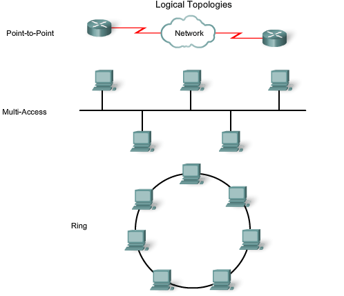
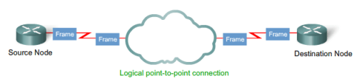
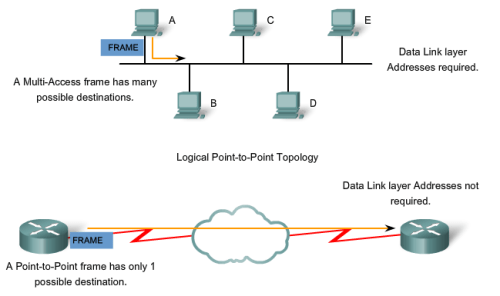
P2P Connection
*Sory untuk Multi Access (pake flash…susah T_T)
Ring Topology Connection (sama ini juga…pake Flash -_-; )
Data Link – Header & Trailer
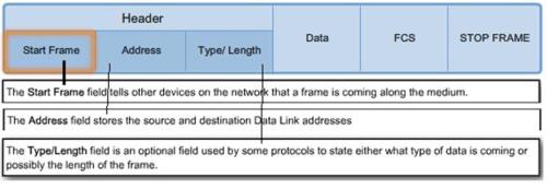
Typical frame header fields include:
- Start Frame field – Indicates the beginning of the frame
- Source and Destination address fields – Indicates the source and destination nodes on the media
- Priority/Quality of Service field – Indicates a particular type of communication service for processing
- Type field – Indicates the upper layer service contained in the frame
- Logical connection control field – Used to establish a logical connection between nodes
- Physical link control field – Used to establish the media link
- Flow control field – Used to start and stop traffic over the media
-
Congestion control field – Indicates congestion in the media
The field names above are nonspecific fields listed as examples. Different Data Link layer protocols may use different fields from those mentioned. Because the purposes and functions of Data Link layer protocols are related to the specific topologies and media, each protocol has to be examined to gain a detailed understanding of its frame structure.
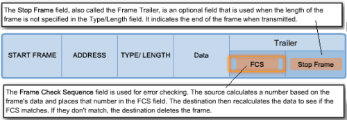
Data Link Frame Trailer
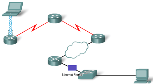
How Data Link Works
Pake gambar aja….
- Laptop Ngirim Data ke Komputer yang paling ujung…Laptop terhubung ke wireless Access Point (AP)…Data Link yang dipakai adalah data link Wireless Frame
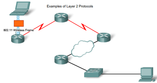
- AP terhubung ke Router…Data Link Frame yang dipakai adalah PPP Frame (Point-to-Point Protocol) ke Router
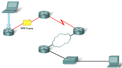
- Router kirim Frame ke Router dengan Frame HDLC (High-level Data Link Control, propiertary Cisco, its seems…Both router are Cisco then 😛 )
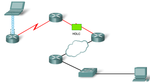
- Router yang ke 2, setelah menerima data link frame HDLC, mengirimkan frame over internet (cloud = Internet) dengan metode Frame Relay
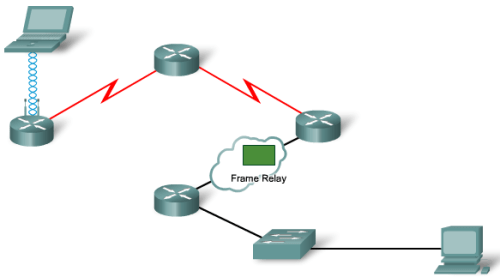
- Sisanya ke Router à Ke Switch à Ke Komputer memakai Ethernet Frame
Sebenernya gw mau bahas tentang Ethernet…tapi di Cisco sendiri ada 1 BAB KHUSUS untuk ini..so nanti aja gw jelasin
Next…gw mo kasi mini-guide (bergambar) tentang Follow Data Through Internetwork

Leave a comment