

The purpose of the Physical layer is to create the electrical, optical, or microwave signal that represents the bits in each frame
Pengiriman Frame dari Data Link ke local medium membutuhkan persyaratan dari Physical Layer berikut :
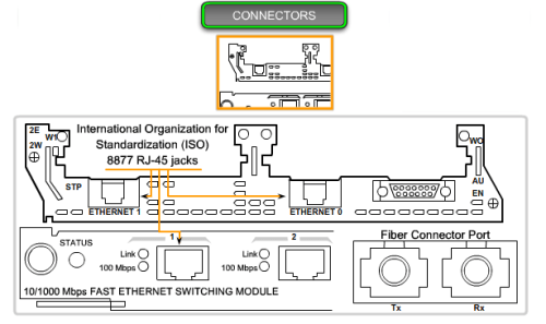
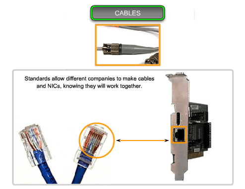
- The physical media and associated connectors
- A representation of bits on the media
- Encoding of data and control information
- Transmitter and receiver circuitry on the network devices
At this stage of the communication process, the user data has been segmented by the Transport layer, placed into packets by the Network layer, and further encapsulated as frames by the Data Link layer
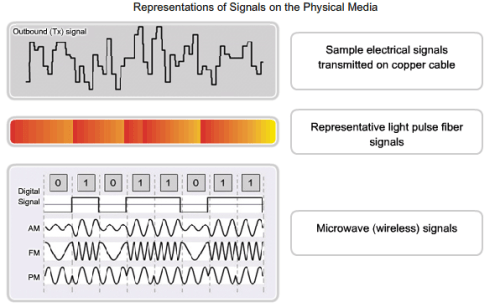
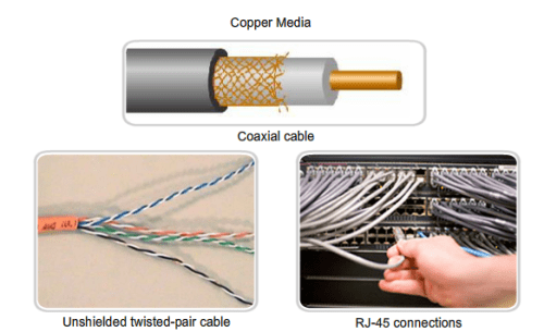
There are three basic forms of network media on which data is represented:
- Copper cable
- Fiber
- Wireless
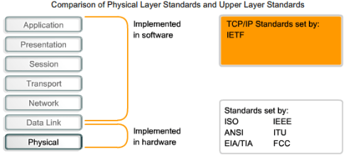
Similar to technologies associated with the Data Link layer, the Physical layer technologies are defined by organizations such as:
- The International Organization for Standardization (ISO)
- The Institute of Electrical and Electronics Engineers (IEEE)
- The American National Standards Institute (ANSI)
- The International Telecommunication Union (ITU)
- The Electronics Industry Alliance/Telecommunications Industry Association (EIA/TIA)
- National telecommunications authorities such as the Federal Communication Commission (FCC) in the USA.
The technologies defined by these organizations include four areas of the Physical layer standards:
- Physical and electrical properties of the media
- Mechanical properties (materials, dimensions, pinouts) of the connectors
- Bit representation by the signals (encoding)
- Definition of control information signals
The three fundamental functions of the Physical layer are:
- The physical components
- Data encoding
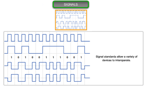
- Signaling
Physical Components: ’nuff said
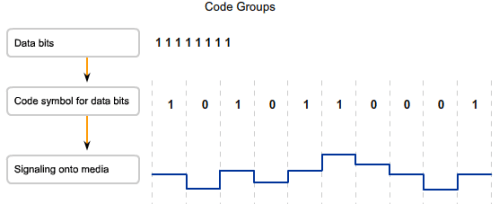
Data Encoding: Encoding is a method of converting a stream of data bits into a predefined code. Codes are groupings of bits used to provide a predictable pattern that can be recognized by both the sender and the received. Using predictable patterns helps to distinguish data bits from control bits and provide better media error detection
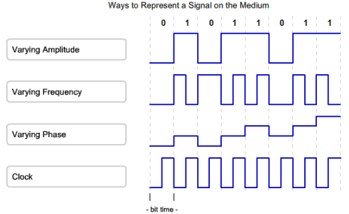
Signaling: The method of representing the bits is called the signaling method, The Physical layer must generate the electrical, optical, or wireless signals that represent the “1” and “0” on the media. (1 = Adanya Listrik alias NYALA, 0 = tidak ada nya listrik alias MATI)
Beberapa cara untuk merepresentasikan sinyal ke medium:
- Membedakan amplitude
- Membedakan frequency
- Membedakan phase
- Membedakan clock rate
Signaling
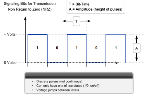
- NRZ Signaling
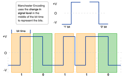
- Manchester Encoding Signaling (10BaseT Ethernet running with this encoding signal !! )
Mengenali Signal Frame dari data link layer
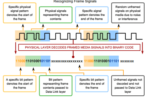
A code group is a consecutive sequence of code bits that are interpreted and mapped as data bit patterns. For example, code bits 10101 could represent the data bits 0011.
Encoding techniques use bit patterns called symbols. The Physical layer may use a set of encoded symbols – called code groups – to represent encoded data or control information
By transmitting symbols, the error detection capabilities and timing synchronization between transmitting and receiving devices are enhanced
Advantages using code groups include:
- Reducing bit level error (They do this by using symbols to ensure that not too many “1” or “0” are used in a row
- Limiting the effective energy transmitted into the media (Transmitting a long series of “1”could overheat the transmitting laser and the photo diodes in the receiver, potentially causing higher error rates)
-
Helping to distinguish data bits from control bits
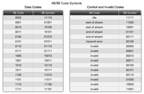
The code groups have three types of symbols:
- Data symbols – Symbols that represent the data of the frame as it is passed down to the Physical layer.
- Control symbols – Special codes injected by the Physical layer used to control transmission. These include end-of-frame and idle media symbols.
- Invalid symbols – Symbols that have patterns not allowed on the media. The receipt of an invalid symbol indicates a frame error.
The symbols encoded onto the media are all unique. The symbols representing the data being sent through the network have different bit patterns than the symbols used for control. These differences allow the Physical layer in the receiving node to immediately distinguish data from control information.
- Better media error detection (In addition to the data symbols and control symbols, code groups contain invalid symbols. These are the symbols that could create long series of 1s or 0s on the media; therefore, they are not used by the transmitting node. If a receiving node receives one of these patterns, the Physical layer can determine that there has been an error in data reception.)
*Intinya dari code group adalah (klo bingung) setiap transmisi data kan pake listrik (contohnya), nah transmisi listrik itu kan “kedap-kedip” tuh…nyala-mati nyala-mati gitu, nah simbol2 untuk nyala dan mati itu 1 dan 0, klo kebanyakan 1 aliasnyala mulu….panas bisa medianya, klo 0 mulu…mati doooonkk, intinya code group ini untuk ENSURE connectivity.
Contoh code group 4b/5b (jujur..gw ga ngerti…wakakak)
Bermain di physical layer berarti kita bermain di bits
BITS = 1 & 0
BYTES = 8 BIT
And the rest are…
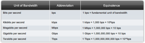
The practical bandwidth of a network is determined by a combination of factors:
- The properties of the physical media
- The technologies chosen for signaling and detecting network signals.
Physical media properties, current technologies, and the laws of physics all play a role in determining available bandwidth
Throughput is the measure of the transfer of bits across the media over a given period of time. Due to a number of factors, throughput usually does not match the specified bandwidth in Physical layer implementations such as Ethernet.
Goodput is the measure of usable data transferred over a given period of time, and is therefore the measure that is of most interest to network users. goodput measures the effective transfer of user data between Application layer entities, such as between a source web server process and a destination web browser device.
Unlike throughput, which measures the transfer of bits and not the transfer of usable data, goodput accounts for bits devoted to protocol overhead. Goodput is throughput minus traffic overhead for establishing sessions, acknowledgements, and encapsulation.
As an example, consider two hosts on a LAN transferring a file. The bandwidth of the LAN is 100 Mbps. Due to the sharing and media overhead
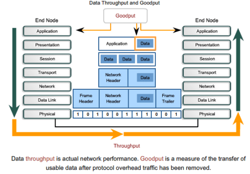
Jadi sebenernya….yg kita bilang cepet nih bandwidthnya, cepet nih transfer datanya…itu adalah Goodput (kita biasa bilang throughput malah). Aktual dari sesi kirim2an datanya adalah throughput
Tipe Media
- Ethernet
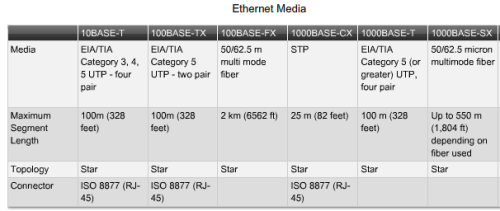
Yang sering kita pake di LAN adalah FastEthernet 100Base-TX (NRZ Encoding), 10BASE-T hanya bisa mentransfer 10Mbit/s walau dengan jarak tempuh yang sama dengan 100Base-TX (yaitu 100 meter)
Sedang 100Base-FX itu adalah kabel fiber optic
1000Base-CX adalah GigabitEthernet (klo FastEthernet biasa kan dari 8 kabel hanya 4 kabel yg dipakai buat tuker2an data / transmisi data, klo Gigabit…8-8 nya dipakai, FastEthernet menggunakan UTP[Unshielded Twisted Pair], sedang 1000Base-CX menggunakan STP /kebalikannya UTP), tipe kabel ini masi dipakai, contoh: IBM Blade Server dengan switching mereka (transmisi tinggi dan jarak yang pendek memungkinkan mereka untuk ensure connectivity, reliability, and speed)
1000Base-T adalah GigabitEthernet JUGA..hanya dengan kabel UTP
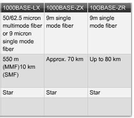
1000Base-SX, 1000Base-LX, 1000Base-ZX, 10GBase-ZR adalah kabel fiber optic (yang membedakan adalah metode pengiriman signal pada kabel fiber optic dan besarnya kabel fiber optic itu sendiri)
*GW POSTING INI PAS WIKIPEDIA LAGI BLACKOUT…ASUUU…..FUCK SOPA !!!
*catatan:
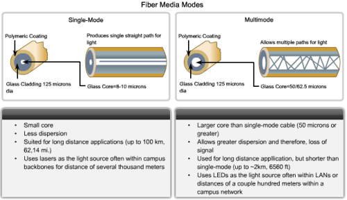
- SMF: Single mode fiber, yaitu teknik pensinyalan dengan hanya mengirimkan 1 “ray” cahaya dalam satu waktu
- MMF: Multi mode fiber, kebalikannya
*dalam teknik mensinyalan di fiber optic, rumit..penuh dengan hukum fisika, ada Helmholtz equation, ada Maxwell’s equations, cari sendiri dah 😆
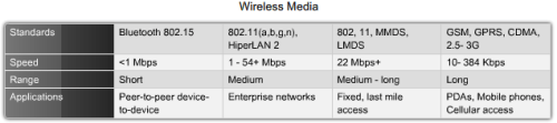
MMDS: Multipoint Multichannel Distribution Service / BRS (Broadband Radio Service)
LMDS: Local Multichannel Distribution Service
penjelasannya dibawah ^_^
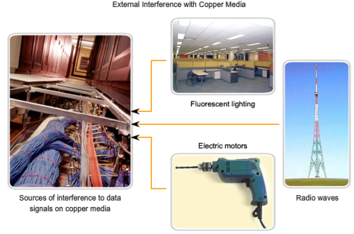
Cable types with shielding or twisting of the pairs of wires are designed to minimize signal degradation due to electronic noise.
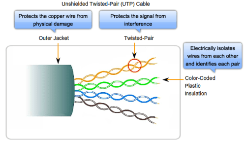
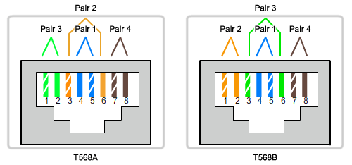
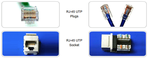
UTP Cable
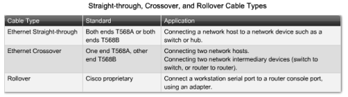
TIA/EIA-568 alias T568A & T568B
Coaxial Cable
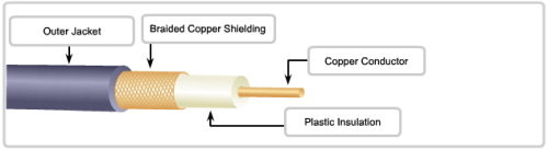
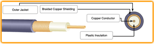
Coaxial is also the most widely used media for transporting high radio frequency signals over wire, especially cable television signals. Traditional cable television, exclusively transmitting in one direction, was composed completely of coax cable.
Untuk Cable ISP, main backbone nya memakai fiber optic, hanya saja, di customer location (modem) dan wiring inside customer’s premises (router / alat ISP yang provide internet ke Modem-nya LANGSUNG) tetap memakai coaxial. Ini yang dinamakan Hybrid Fiber Coax (HFC)
STP
Shielded Twisted Pair ini walaupun sudah digantikan fungsinya dengan UTP, tapi beberapa perusahaan masih ada yang memakai STP (contoh: IBM)
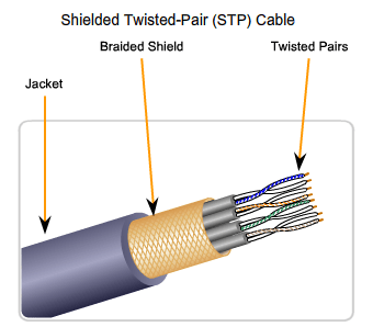
STP cable shields the entire bundle of wires within the cable as well as the individual wire pairs. STP provides better noise protection than UTP cabling, however at a
significantly higher price.
Fiber Optic
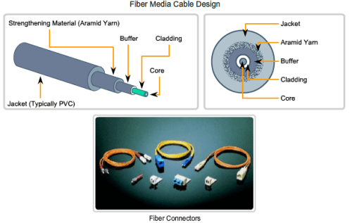
Given that the fibers used in fiber-optic media are not electrical conductors, the media is immune to electromagnetic interference and will not conduct unwanted electrical currents due to grounding issues. Because optical fibers are thin and have relatively low signal loss, they can be operated at much greater lengths than copper media, without the need for signal regeneration. Some optical fiber Physical layer specifications allow lengths that can reach multiple kilometers.
Optical fiber media implementation issues include:
- More expensive (usually) than copper media over the same distance (but for a higher capacity)
- Different skills and equipment required to terminate and splice the cable infrastructure
- More careful handling than copper media
At present, in most enterprise environments (mainly ISP), optical fiber is primarily used as backbone cabling for high-traffic point-to-point connections between data distribution facilities and for the interconnection of buildings in multi-building campuses. Because optical fiber does not conduct electricity and has low signal loss, it is well suited for these uses.
Karena serat fiber optic HANYA BISA mentransmit cahaya SATU arah, maka untuk full duplex mode harus membutuhkan 2 serat fiber
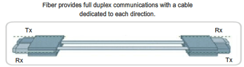
- SMF (Single-mode optical fiber) carries a single ray of light, usually emitted from a laser. Because the laser light is uni-directional and travels down the center of the fiber, this type of fiber can transmit optical pulses for very long distances.
- MMF (Multimode fiber) typically uses LED emitters that do not create a single coherent light wave. Instead, light from an LED enters the multimode fiber at different angles. Because light entering the fiber at different angles takes different amounts of time to travel down the fiber, long fiber runs may result in the pulses becoming blurred on reception at the receiving end. This effect, known as modal dispersion, limits the length of multimode fiber segments.
Multimode fiber, and the LED light source used with it, is cheaper than single-mode fiber and its laser-based emitter technology.
Wireless
The IEEE and telecommunications industry standards for wireless data communications cover both the Data Link and Physical layers. Four common data communications standards that apply to wireless media are:
- Standard IEEE 802.11 – Commonly referred to as Wi-Fi, is a Wireless LAN (WLAN) technology that uses a contention or non-deterministic system with a Carrier Sense Multiple Access/Collision Avoidance (CSMA/CA) media access process.
- Standard IEEE 802.15 – Wireless Personal Area Network (WPAN) standard, commonly known as “Bluetooth“, uses a device pairing process to communicate over distances from 1 to 100 meters.
- Standard IEEE 802.16 – Commonly known as Worldwide Interoperability for Microwave Access (WiMAX), uses a point-to-multipoint topology to provide wireless broadband access.
- Global System for Mobile Communications (GSM) – Includes Physical layer specifications that enable the implementation of the Layer 2 General Packet Radio Service (GPRS) protocol to provide data transfer over mobile cellular telephony networks.
Other wireless technologies such as satellite communications provide data network connectivity for locations without another means of connection. Protocols including GPRS enable data to be transferred between earth stations and satellite links.
In each of the above examples, Physical layer specifications are applied to areas that include:
- data to radio signal encoding
- frequency and power of transmission
- signal reception and decoding requirements
- and antenna design and construction.
A common wireless data implementation is enabling devices to wirelessly connect via a LAN. In general, a wireless LAN requires the following network devices:
- Wireless Access Point (AP) – Concentrates the wireless signals from users and connects, usually through a copper cable, to the existing copper-based network infrastructure such as Ethernet.
- Wireless NIC adapters – Provides wireless communication capability to each network host.

Wireless Wi-Fi Standard
- IEEE 802.11a – Operates in the 5 GHz frequency band and offers speeds of up to 54 Mbps. Because this standard operates at higher frequencies, it has a smaller coverage area and is less effective at penetrating building structures. Devices operating under this standard are not interoperable with the 802.11b and 802.11g standards described below.
- IEEE 802.11b – Operates in the 2.4 GHz frequency band and offers speeds of up to 11 Mbps. Devices implementing this standard have a longer range and are better able to penetrate building structures than devices based on 802.11a.
- IEEE 802.11g – Operates in the 2.4 GHz frequency band and offers speeds of up to 54 Mbps. Devices implementing this standard therefore operate at the same radio frequency and range as 802.11b but with the bandwidth of 802.11a.
- IEEE 802.11n – The IEEE 802.11n standard is currently in draft form. The proposed standard defines frequency of 2.4 Ghz or 5 GHz. The typical expected data rates are 100 Mbps to 210 Mbps with a distance range of up to 70 meters.
The benefits of wireless data communications technologies are evident, especially the savings on costly premises wiring and the convenience of host mobility. However, network administrators need to develop and apply stringent security policies and processes to protect wireless LANs from unauthorized access and damage
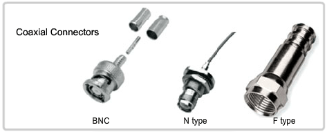
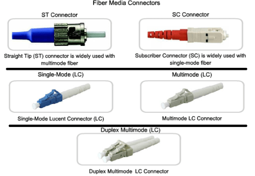
Connector

Leave a comment